Wireman
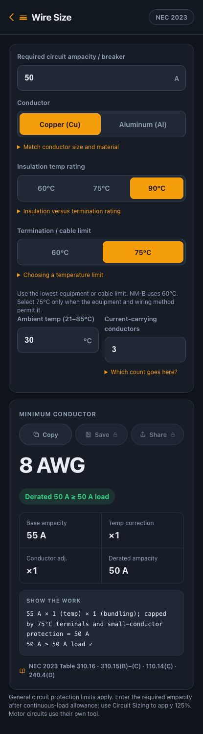
For this 50 A example, Wireman selects 8 AWG copper with permitted 75°C terminations. Change only the termination limit to 60°C and the result becomes 6 AWG. A 90°C insulation marking does not make every connected terminal suitable for 90°C ampacity.
The example and its assumptions
Consider a general circuit with a required conductor ampacity of 50 A. That is the design requirement already established for the circuit, including any applicable continuous-load allowance—not an instruction to put an arbitrary 50 A load on any installation.
| Required circuit ampacity / breaker | 50 A |
|---|---|
| Conductor | Copper |
| Insulation temperature rating | 90°C |
| Termination / cable limit | 75°C, permitted at every applicable connection |
| Ambient temperature | 30°C |
| Current-carrying conductors | 3 |
This example assumes a wiring method that permits these ratings and no additional installation-specific derating. It does not use a motor exception, a next-size-up breaker rule or a dwelling-service allowance.
Work through the temperature limit
For 8 AWG copper, the relevant table values are 55 A at 90°C and 50 A at 75°C. Southwire’s THHN/THWN-2 engineering data corroborates those two values and identifies NEC 2023 Table 310.16 as its basis.
At 30°C with three current-carrying conductors, this example uses factors of 1.00 for both ambient temperature and conductor count. The 75°C termination then limits the usable value:
Insulation-based value: 55 A × 1.00 × 1.00 = 55 A
Termination limit: 50 A
Usable ampacity: min(55 A, 50 A) = 50 A
The app therefore displays 8 AWG and 50 A derated ampacity. Its “derated” label includes the termination cap, even though the two adjustment factors are 1.
What if the termination is only 60°C?
Keep the same inputs and select 60°C for the termination/cable limit. The 60°C value for 8 AWG copper is 40 A, below the required 50 A. The next size, 6 AWG, has a 60°C value of 55 A. Wireman selects 6 AWG, limited to 55 A. These values come from the supported Table 310.16 rows; see the NFPA table reproduction, page 2. The linked document is a proposal; this example uses only its unchanged existing copper rows.
Check actual equipment markings. Schneider Electric explains why ignoring the termination rating can lead to excess heating in its wire temperature and termination bulletin.
Before using the result
- Establish required ampacity first. Wire Size does not automatically add 125% for a continuous load.
- Use the lowest applicable equipment or cable limit. A warmer location or additional current-carrying conductors can change the result.
- Check voltage drop separately; adequate ampacity does not guarantee acceptable voltage at the load.
- Confirm the wiring method, overcurrent protection and adopted code. A general sizing example does not cover every installation exception.
Code basis: NEC 2023 Table 310.16, 310.15(B)–(C), 110.14(C) and 240.4(D). Consult NFPA 70 and your locally adopted requirements.
About this example
Original worked example prepared for Wireman. Arithmetic and displayed outputs were checked against the app’s calculation engine on 24 September 2026. This is a product explanation, not an independently certified electrical design or a licensed professional review. Verify your installation against the adopted code, equipment instructions and local amendments.