Wireman
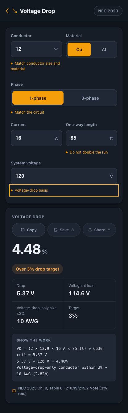
For 16 A over an 85 ft one-way run at 120 V, Wireman estimates 4.48% drop with 12 AWG copper. Using 10 AWG reduces that estimate to 2.82%. The larger size meets the app’s 3% voltage-drop target; its ampacity and installation suitability still need a separate check.
Set up the example
Assume a single-phase, two-wire circuit carrying 16 A. The routed distance from the source to the load is 85 ft. We compare conductor sizes while holding the current, distance and supply voltage constant.
| Conductor | 12 AWG |
|---|---|
| Material | Copper |
| Phase | 1-phase |
| Current | 16 A |
| One-way length | 85 ft |
| System voltage | 120 V |
Calculate the drop
Wireman uses the simplified circular-mil resistance method. For this single-phase example, VD = 2 × K × I × L ÷ CM. K is 12.9 for copper, I is load current, L is one-way length, and CM is conductor area in circular mils. The factor of two already accounts for the outgoing and return paths. See Mike Holt’s published formulas and constants.
12 AWG area = 6,530 circular mils
VD = (2 × 12.9 × 16 × 85) ÷ 6,530
VD ≈ 5.3734 V
Drop = 5.3734 ÷ 120 × 100 ≈ 4.48%
Voltage at load ≈ 114.6 V
The app displays 5.37 V and 4.48%. It calculates with unrounded values before formatting the answer; recomputing from a rounded voltage can differ slightly in the final decimal.
Compare one size larger
Change Conductor to 10 AWG and leave the other inputs alone. With 10,380 circular mils, the same equation gives approximately 3.38 V, or 2.82%. Wireman identifies 10 AWG as the smallest size in its supported table that meets this example’s 3% target.
| Copper size | Drop | Percentage | At load |
|---|---|---|---|
| 12 AWG | 5.37 V | 4.48% | 114.6 V |
| 10 AWG | 3.38 V | 2.82% | 116.6 V |
What the 3% result does—and does not—mean
The app uses 3% as a comparison target, not as a universal declaration that an installation complies with the NEC. Equipment requirements, upstream feeder drop and the applicable code can change the design criteria. The “voltage-drop-only size” is not a breaker recommendation.
This K-method estimate does not model power factor, reactance, changing conductor temperature, motor starting or parallel conductors. More detailed AC analysis can differ, particularly with large conductors. Mike Holt’s voltage-drop explanation discusses the method’s assumptions and AC resistance adjustments.
Two easy input mistakes
- Doubling the length. Enter 85 ft, not 170 ft; the single-phase formula already includes the return path.
- Using breaker rating as load current automatically. Use a documented operating or design-current assumption. This example uses 16 A, rather than silently substituting a 20 A breaker rating.
Then use Wire Size or Circuit Sizing for the separate ampacity and protection check, including temperature limits. Record both sets of assumptions with the job.
Reference basis: the app cites NEC 2023 Chapter 9 Table 8 and the voltage-drop informational notes associated with 210.19 and 215.2. Consult NFPA 70 for the adopted requirements; this is a simplified calculation example.
About this example
Original worked example prepared for Wireman. Arithmetic and displayed outputs were checked against the app’s calculation engine on 24 September 2026. This is a product explanation, not an independently certified electrical design or a licensed professional review. Verify your installation against the adopted code, equipment instructions and local amendments.